
Zoetrope
Design & Manufacturing
Challenge
For my ME203 class, we were asked to design and build something of personal significance, that would let us gain depth in at least one of the four main manufacturing methods we learned
Concept
I designed an built a Zoetrope -- an device that that produces the illusion of motion in a strip of sequenced frames -- aimed at helping budding animators practice drawing frame by frame animation
Skills & Tools
-
Design - SolidWorks
-
Prototyping - Laser Cutting, 3D Printing, Cardboard & Foam Core
-
Fabrication - Lathe, Mill
Timeline
January - March 2020
Background

Growing up, I was very excited by the idea of becoming an animator. I'd often dream about creating the next amazing show inspired by what I was seeing on Cartoon Network

However, any time I sat down to draw, the task of animating felt so large and inaccessible: where could I even start? This stopped me from making any tangible progress

Having a Zoetrope would have given me access to a more manageable bitesize task: learning the basics of frame by frame animation. I could practice drawing a sequence of frames to create a range of motion

The Zoetrope would "play" my motion sequence and give me the opportunity to observe strengths and areas for growth. This would allow me to refine my skills to a point where I was ready to take on larger tasks.
Key Features
The Zoetrope's core function is to "display" the animation of a strip of sequenced frames through rotational motion of the body about the stand. As such, stable and friction-less rotation about its axis is key to an ideal viewing experience

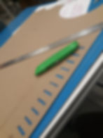
The Zoetrope accommodates a strip of nine 3.5cm x 3.5cm frames, with a little tab at the end that allows the strip to be taped together. I tested a couple of frame sizes and selected the smallest size that didn't feel cramped. The walking animation cycle is a common entry point for beginner animators, and in a lot of cases, the sequence is broken down to 9 frames as seen below

Initial Design and Scoping
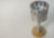
Both forming and Machining could have gotten me to the final geometry that I needed for the Zoetrope "Drum" (seen below) where the strip sits. While forming could have gotten me to the final geometry quicker, my abilities on the lathe far exceeded my welding abilities, so I chose to proceed with machining to put myself in the best position to achieve a quality finish

Initial Assembly Design Intent:
-
Stand screws in and out of base
-
Stand has two threaded regions at the top separated by shaft about which the drum rotates
-
The wheels have internal threads, and are fastened onto stand above and below the drum to secure the drum's position along the stand's axis
-
Wheels should be as small as acceptable to minimize friction with drum during rotation


Prototypes
Through the prototypes, I wanted to answer:
-
How well does the Zoetrope Drum spin?
-
Are the joints functional?

Tabs at the bottom used to secure the cardboard to the drum base


Insights:
-
Spin direction decides whether animation is played in correct or reverse directions: threaded joints (and parts 1&3) should be eliminated to avoid spinning in the direction that could loosen the threads and disassemble the assembly
-
The spinning was unstable: there was a lot of teetering about center point as seen in the video. This didn't compromise the quality of the animation however once the part was machined out of heavier metal, this wobbling could compromise the Zoetrope's ability to remain upright.
User Testing Insights:
-
Assembly knocked over several times when spun too aggressively -- consider increasing base thickness for added stability
-
Action of spinning is quite tedious -- can it spin on its own or for a longer time?
-
consider making it taller not entirely pleasant to bend over and look through
(sound on)
Design Updates

Fabrication Gallery


Final Part
Unfortunately due to COVID-19, I wasn't able to finish the entire assembly, but I had enough parts completed to see functional animations

Learnings/Reflection:
-
Better to design with imperial units when using catalog parts that are dimensioned in imperial units
-
An assembly tolerance check is always helpful before manufacturing begins
-
Would be interesting to build gears and a crank into the assembly like below so the user has more control over the motion and speed for a better experience.
